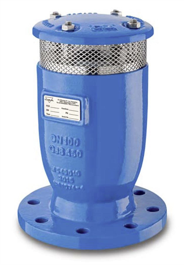
AIR RELIEF VALVE, ANTI-SLAM, EN1092, 16-40 BAR
Lynx 3F-AS, red. bore for clean water, A2 Delta Seal GZ fasteners, 250µm blue RAL5005 EP coating

Contact
AVK Valves India Pvt Ltd
117 & 118, 1st Floor, Road Number 3 Vijayanagar, EPIP Phase I, Whitefield, Bengaluru, Karnataka 560066, India
Air relief valve for clean water and neutral liquids to max., 70°C. Used in applications as transmission lines, water distribution networks and for irrigation.
AVK anti water hammer combination air valves ensure the proper operation of the pipeline network allowing the release of air pockets during working conditions, the entrance of large volumes of air during draining operations and pipeline bursts. The air is discarged with controlled speed, to prevent water hammer. The valve is generally used near pumps, where there are changes in slope ascending and at high points where the pipeline is subjected to water hammer.
| Variant 861/11-001 | |
|---|---|
| Connection: | No connection type specified |
| Material: | Ductile iron |
| DN: | DN50 - DN400 |
| PN: | PN 40 |
Features
- Single chamber body in ductile cast iron, PN40 bar rated.
- Internal ribs ensure a consistant and accurate guiding of the mobile block.
- Drainage valve for chamber control and pressurerelief during maintenance.
- Mobile block made of a cylindrical float and upper disc in solid polyprolylene, joined together by the air release system in AISI 316. The cylindrical floats are solid which prevents deformation and ensure great precision when moving inside the chamber.
- Nozzle and gasket holder are wear resistant due to the gasket compression control.
- Easy maintenance without removing the air valve from the pipesystem.
- The Anti water hammer system consists of a spring and shaft in stainless steel and a disc with adjustable sonic nozzels for control of the air flow and it is quickly open at vacuum condition and allows the large amount of air intake and break the vacuum.
- Cover in ductile iron and screen in stainless steel prevents materials and insects entering the valve. Outlet for submerged applications are optional.
- Working conditions 0,2 - 40 bar differential pressure.
Downloads
Reference nos. and dimensions:
| Reference no. | DN mm |
Flange drilling |
PN Class |
L mm |
H3 mm |
Theoretical weight/kg |
Notes |
|---|---|---|---|---|---|---|---|
| 861-0050-11-0111 | 50 | PN16 | PN16 | 165 | 236 | 7.0 | |
| 861-0050-11-0911 | 50 | PN16 | PN10 | 117 | 231 | 5.0 | 2" BSP thread |
| 861-0050-11-1711 | 50 | PN25 | PN25 | 165 | 236 | 7.0 | |
| 861-0050-11-1911 | 50 | PN25 | PN25 | 117 | 231 | 5.0 | 2" BSP thread |
| 861-0050-11-2811 | 50 | PN40 | PN40 | 165 | 236 | 7.0 | |
| 861-0050-11-2911 | 50 | PN40 | PN40 | 117 | 231 | 5.0 | 2" BSP thread |
| 861-0080-11-0111 | 80 | PN16 | PN16 | 210 | 305 | 11 | |
| 861-0080-11-1711 | 80 | PN25 | PN25 | 210 | 305 | 11 | |
| 861-0080-11-2811 | 80 | PN40 | PN40 | 210 | 305 | 11 | |
| 861-0100-11-0111 | 100 | PN16 | PN16 | 235 | 303 | 14 | |
| 861-0100-11-1711 | 100 | PN25 | PN25 | 235 | 303 | 14 | |
| 861-0100-11-2811 | 100 | PN40 | PN40 | 235 | 303 | 14 | |
| 861-0150-11-0111 | 150 | PN16 | PN16 | 305 | 337 | 23 | |
| 861-0150-11-1711 | 150 | PN25 | PN25 | 305 | 337 | 23 | |
| 861-0150-11-2811 | 150 | PN40 | PN40 | 305 | 337 | 23 | |
| 861-0200-11-0011 | 200 | PN10 | PN10 | 375 | 515 | 55 | |
| 861-0200-11-0111 | 200 | PN16 | PN16 | 375 | 515 | 55 | |
| 861-0200-11-1711 | 100 | PN25 | PN25 | 375 | 515 | 55 | |
| 861-0200-11-2811 | 200 | PN40 | PN40 | 375 | 515 | 55 | |
| 861-0250-11-0011 | 250 | PN10 | PN10 | 450 | 625 | 101 | |
| 861-0250-11-0111 | 250 | PN16 | PN16 | 450 | 625 | 101 | |
| 861-0250-11-1711 | 100 | PN25 | PN25 | 450 | 625 | 101 | |
| 861-0250-11-2811 | 250 | PN40 | PN40 | 450 | 625 | 101 | |
| 861-0300-11-0011 | 300 | PN10 | PN10 | 485 | 735 | 127 | |
| 861-0300-11-0111 | 300 | PN16 | PN16 | 485 | 735 | 127 | |
| 861-0300-11-1711 | 100 | PN25 | PN25 | 485 | 735 | 127 | |
| 861-0300-11-2811 | 300 | PN40 | PN40 | 485 | 735 | 127 | |
| 861-0350-11-0011 | 350 | PN10 | PN10 | 580 | 850 | 251 | |
| 861-0350-11-0111 | 350 | PN16 | PN16 | 580 | 850 | 251 | |
| 861-0350-11-1711 | 100 | PN25 | PN25 | 580 | 850 | 251 | |
| 861-0350-11-2811 | 350 | PN40 | PN40 | 580 | 850 | 251 | |
| 861-0400-11-0011 | 400 | PN10 | PN10 | 660 | 995 | 304 | |
| 861-0400-11-0111 | 400 | PN16 | PN16 | 660 | 995 | 304 | |
| 861-0400-11-1711 | 100 | PN25 | PN25 | 660 | 995 | 304 | |
| 861-0400-11-2811 | 400 | PN40 | PN40 | 660 | 995 | 304 |
Components


| 1. | Body | Ductile iron GJS-450-10 |
| 2. | Cap | Ductile iron GJS-450-10 |
| 3. | O-ring | NBR rubber |
| 4. | O-ring | NBR rubber |
| 5. | Seat | Stainless steel AISI 304 |
| 6. | Nozzle | Stainless steel AISI 316 |
| 7. | Upper part | Polypropylene |
| 8. | Float | Polypropylene |
| 9. | Studs | Stainless steel A2 |
| 10. | Nuts | Stainless steel A2 |
| 11. | Spacer | Stainless steel AISI 304 |
| 12. | Nuts | Stainless steel A2 |
| 13. | Washer | Stainless steel A2 |
| 14. | Disc | Stainless steel AISI 304 |
| 15. | Nuts | Stainless steel A2 |
| 16. | Drain valve | Stainless steel AISI 303 |
| 17. | Screen | Stainless steel AISI 304 |
| 18. | Nut | Stainless steel A2 |
| 19. | Spring | Stainless steel A2 |
| 20. | Shaft | Stainless steel AISI 304 |
| 21. | Disc | Stainless steel AISI 304 |
| 22. | Label | Stainless steel AISI 304 |
Test/Approvals
- Hydraulic test according to EN 1074-1 and 4 / EN 12266
- Approved according to EN 1074-1 and 4
Standards
- AWWA C512, EN 1074 part 1
- Flange drilling to EN1092, PN10/16/25/40